")
Product Overview
SRM drives have no permanent magnets and no rotor windings; all performance aspects are highly dependent on the driver's current modeling capabilities, switching strategies, and real-time control accuracy.
AURIC SRM drives are designed from a system-level perspective, going beyond simple power amplifiers. They focus on addressing torque ripple control, low-speed start-up stability, high-speed commutation accuracy, and reliable operation under high temperature and voltage fluctuations.
Product Advantages
Current Control Architecture
Utilizes high-speed current sampling and closed-loop control
Precisely controls the conduction and turn-off angles of each phase
Supports a combination of chopper control and angle control
SRM torque = current × reluctance rate. Poor control leads to large torque fluctuations, high noise, and decreased efficiency.
The driver determines the usability of the SRM.
Power Devices and Heat Dissipation Technology
Industrial-grade IGBT/MOSFET modules
Independent phase power topology design
Thick copper PCB + low thermal resistance heat dissipation structure
Less prone to failure under high current surges
More stable operation under long-term full load
Commutation and Control Algorithm Differences
Adaptive commutation strategy, adaptable to different speed ranges
Optimized torque ripple suppression algorithm
Reduces low-speed crawling and howling issues
Not just able to rotate, but to rotate controllably, adjustablely, and for long-term use
Environmental Resistance
No risk of permanent magnet demagnetization
Can operate in high temperature, high dust, and high vibration environments
Wide voltage input, adaptable to grid fluctuations
Product Craftsmanship
Our products utilize a multi-layer PCB design, significantly reducing electromagnetic interference.
The power and control partitioning layout enhances stability.
Critical solder joints undergo 100% inspection.
Load aging tests are performed before shipment.
High batch consistency and low after-sales risk.
Outline Dimension Table
| Controller Selection and Dimensions | ||||||
| Type | Rated | Input | Rated Output | Short-time | Overall Dimensions mm) | Weight |
| Power (kW) | Current (A) | Current (A) | Output Current (A) | Width × Depth × Height | ( kg) | |
| ASC20-11-T3 | 11 | 19 | 9 | 13 | 368x300x500 | 32 |
| ASC20-15-T3 | 15 | 26 | 12 | 18 | 368x300x500 | 37 |
| ASC20-18.5-T3 | 18.5 | 32 | 14 | 21 | 368x300x500 | 39 |
| ASC20-22-T3 | 22 | 37 | 17 | 25 | 368x300x500 | 42 |
| ASC20-30-T3 | 30 | 51 | 23 | 34 | 411x297x710 | 49 |
| ASC20-37-T3 | 37 | 62 | 28 | 41 | 411x297x710 | 52 |
| ASC20-45-T3 | 45 | 75 | 33 | 50 | 411x297x710 | 54 |
| ASC20-55-T3 | 55 | 92 | 41 | 61 | 468x272x850 | 64 |
| ASC20-75-T3 | 75 | 124 | 55 | 83 | 468x272x850 | 68 |
| ASC20-90-T3 | 90 | 149 | 66 | 99 | 485x272x960 | 84 |
| ASC20-110-T3 | 110 | 181 | 80 | 120 | 485x272x960 | 89 |
| ASC20-132-T3 | 132 | 217 | 95 | 143 | 619x279x1000 | 109 |
| ASC20-160-T3 | 160 | 262 | 114 | 171 | 619x279x1000 | 114 |
| ASC20-180-T3 | 180 | 295 | 128 | 193 | 1000x650x1854 | 336 |
| ASC20-200-T3 | 200 | 327 | 143 | 214 | 1000x650x1854 | 347 |
| ASC20-220-T3 | 220 | 360 | 157 | 235 | 1000x650x1854 | 363 |
| ASC20-250-T3 | 250 | 409 | 178 | 267 | 1000x650x1854 | 382 |
| ASC20-280-T3 | 280 | 457 | 199 | 299 | 1000x622x2037 | 656 |
| ASC20-315-T3 | 315 | 514 | 224 | 336 | 1000x622x2037 | 676 |
| ASC20-355-T3 | 355 | 579 | 252 | 379 | 1000x622x2037 | 692 |
| ASC20-400-T3 | 400 | 653 | 284 | 427 | 1200x800x2137 | 825 |
| ASC20-450-T3 | 450 | 734 | 320 | 480 | 1200x800x2137 | 844 |
| ASC20-500-T3 | 500 | 816 | 356 | 533 | 1200x800x2137 | 865 |
Performance parameter table
| Controller Technical Data | |||||||
| Item | Requirements & Functions | ||||||
| Power Input | Input Voltage | 3-phase AC 380V, 415V, 660V, 1140V | |||||
| Frequency | 50Hz or 60Hz | ||||||
| Functions & Parameters | Rated Power | 4~500kW | |||||
| Speed Setting | Three methods: operation panel setting, analog setting, communication setting | ||||||
| Start/Stop Control | Three methods: operation panel control, switch input control,communication | ||||||
| control. | |||||||
| Feedback Speed Regulation | Can be connected to external signals such as pressure and temperature to | ||||||
| form closed-loop feedback control | |||||||
| Speed Accuracy | ≤0.1% | ||||||
| Speed Change Rate | ≤1% | ||||||
| Forward/Reverse | ≥1000 times/hour | ||||||
| Communication Port | RS232, RS485, CAN | ||||||
| PID | Built-in speed and feedback PID control with configurable parameters | ||||||
| I/O Interface | 6-channel digital input, 4-channel digital output, 4-channel analog input, | ||||||
| 2-channel analog output, expandable | |||||||
| Protection Function | Provides protection against short circuit, overcurrent, overload, locked rotor, | ||||||
| overheating, overvoltage, undervoltage and overspeed | |||||||
| Display | Panel: speed display, parameter display, fault code display, operation data | ||||||
| display, etc. Supports external touch screen with programmable display content | |||||||
| Overload Capacity | 200% rated torque for 60s; 120% rated torque for 1 hour | ||||||
| Cycle Time | 300s, average power within the cycle shall not exceed rated power | ||||||
| Operating Environment | Application Site | No direct sunlight, no conductive dust, no excessive dust, no acid/alkali or | |||||
| corrosive gases, no explosive gases | |||||||
| Altitude | Not exceeding 1000m; derate if exceeding 1000m | ||||||
| Operating Temperature | -5℃~+40℃, no frost | ||||||
| Operating Humidity | Not exceeding 90% (20℃), no condensation | ||||||
| Vibration | Less than 5 m/s | ||||||
| Duty Cycle | S1 | ||||||
| Structure | Installation Structure | 11~160kW: wall-mounted; 200~500kW: floor-standing cabinet type | |||||
| Cooling Method | 11~250kW: forced air cooling; 280~500kW: industrial air conditioning cooling | ||||||
| Protection Grade | 11~160kW: IP20; 200~250kW: IP51; 280~500kW: IP54 | ||||||
| Standard | Controller Standard | Enterprise Standard: Q/0303SKH 062-2012 | |||||
Why Choose Us
1.AURIC has long been involved in the development of switched reluctance motor (SRM) applications, possessing a deep understanding of magnetic circuit characteristics, torque formation mechanisms, and commutation logic. We don't produce general-purpose drives; we manufacture control systems optimized for SRM characteristics.
2.Many SRM projects fail not because of the motor itself, but mostly because of mismatch between the drive and the motor.
We can jointly optimize motor parameters and SRM drive control strategies based on actual operating conditions.
3.All SRM drives undergo load testing before leaving the factory.
Key power modules and control boards undergo zone testing.
Batch parameter consistency is controllable.
Reduce after-sales and field issues, avoiding hidden costs.
4.Supports OEM/ODM engineering collaboration.
Supports customization of control logic and interface methods.
Protection strategies can be adjusted according to application conditions.
Provides complete technical documentation and parameter specifications.
Shipping & Packaging
Export-grade professional packaging
Anti-static inner packaging to protect control circuits
Customized foam or cushioning structure to prevent vibration and impact
Reinforced outer carton, suitable for sea freight and long-distance transport
Reduces transport damage rate and minimizes delivery disputes
Flexible shipping options
Supports small-batch sample and bulk order shipments
Can deliver in batches according to project schedule
Compatible with multiple international logistics methods
Export experience and documentation support
Familiar with export procedures for motors and drive products
Can provide technical documents and test reports
Packaging and labeling meet international market requirements
Helps buyers reduce customs clearance and compliance risks
Technical Support
Provides parameter setting and debugging guidance
Engineers support drive and SRM motor matching
Long-term technical response, supporting project iterations
We prioritize the stable operation of equipment at your customer's site.
FAQ
If your application environment has extremely high requirements for temperature, reliability, and maintenance cycles, SRM drives will be a more rational choice.
Contact AURIC for SRM motor and drive matching solutions.
Control Circuit
The ASC20 series switched reluctance motor controller mainly consists of a main control board, a drive board, a display board, a power electronic main circuit, and control software.
The main control board adopts a new-type DSP chip as the core controller, paired with an FPGA for I/O expansion and circuit logic control. The drive board receives control signals from the main control board and converts them into drive signals for the IGBTs in the main circuit to regulate the main circuit's operation. The display board allows users to view the motor's operating data and parameter settings.
The controller features keyboard input functionality, enabling motor start/stop control and parameter configuration. It provides analog and digital interfaces to input sensor and switch signals, and output analog and relay signals, supporting basic PLC control functions. Additionally, it integrates RS232, RS485, and CAN communication interfaces for convenient remote monitoring by users.
System Characteristics
- High starting torque, low starting current: When the starting torque reaches 150% of the rated torque, the starting current is only 30% of the rated current.
- Frequent start-stop and forward/reverse switching capability: With a braking unit and sufficient braking power, start-stop and forward/reverse switching can be performed over 1,000 times per hour.
- Strong overload capacity: The motor's starting torque exceeds 3 times the rated torque. Equipped with internal temperature sensors, the motor fully utilizes its overload capacity as long as the temperature remains within limits.
- High efficiency and excellent energy-saving performance: Across a wide speed regulation range, the overall efficiency is at least 10% higher than other speed control systems, with even more pronounced high efficiency at low speeds and under non-rated loads.
- High power factor: The power factor exceeds 0.9 under both no-load and full-load conditions.
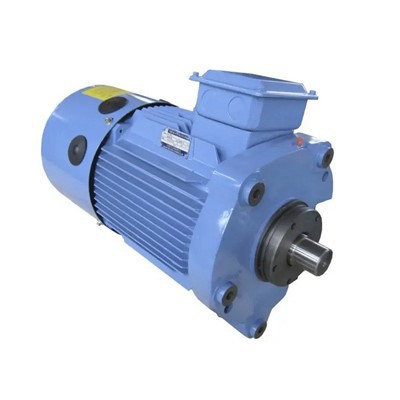
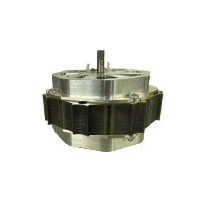
- Simple motor structure and strong impact resistance: The motor rotor is made of stacked silicon steel sheets, with no cast aluminum, windings, or permanent magnets. Its high mechanical strength enables long-term tolerance of strong impacts and vibrations during spiral press operation.
- High controller reliability: The motor's power switching devices are connected in series with the windings, eliminating through-fault risks and making the reliability higher than that of the three-phase bridge circuit in frequency converters.
Application Scenarios of ASC20 Series Switched Reluctance Motor Speed Control Systems
- General machinery: Fans, water pumps, oil pumps, compressors, etc.
- Textile machinery: Rapier looms, towel looms, etc.
- Oilfield machinery: Vertical oil pumps, beam pumping units, well testing machines, etc.
- Coal mining machinery: Coal shearers, endless rope winches, roadheaders, ball mills, crushers, etc.
- Press machinery: Spiral presses (brick presses), mechanical presses, etc.
- Machine tools: Gantry planers, vertical lathes, drilling machines, etc.
- Transportation vehicles: Electric vehicles
- Food machinery: Discharge machines, mixers, blenders, etc.
- Lifting machinery: Elevators, winches, hoists, conveyor belts, etc.
- Power generation equipment: Wind power generation
- Plastic machinery: Extruders, injection molding machines, etc.
- Foundry machinery: Shot blasting machines, etc.
- Paper machinery: Paper machines, calenders, paper rewinders, etc.
- Glass machinery: Bottle-making machines, etc.
- Metallurgical machinery: Steel rolling mills, etc.
- Auxiliary machinery: Coilers, uncoilers, wire laying machines, etc.
- Household appliances: Washing machines, vacuum cleaners, etc.
Hot Tags: srm drives, China srm drives manufacturers, suppliers, factory